PCM1704 Fully Discrete True Balance Output Decoder (Commemorative Edition)
Overall architecture:
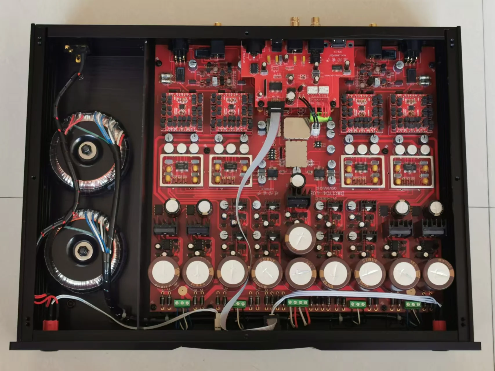
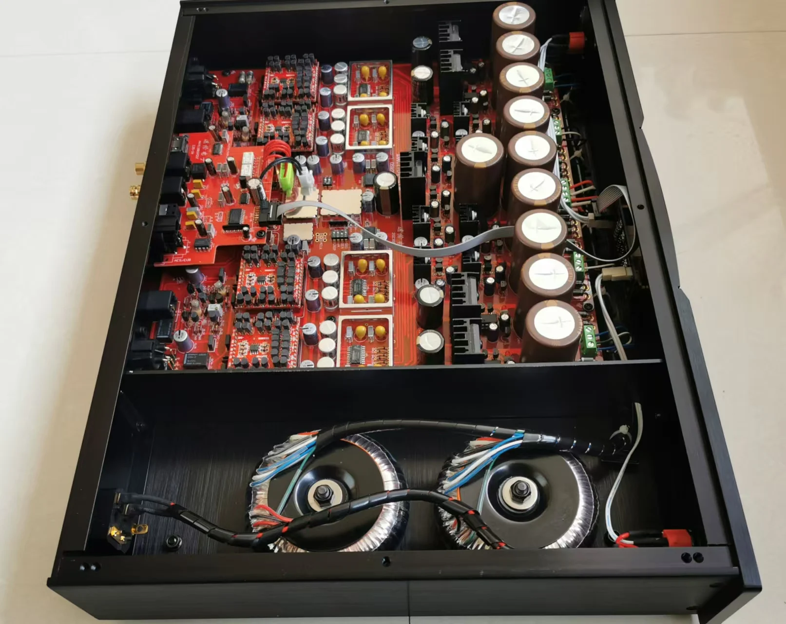
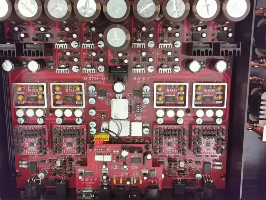
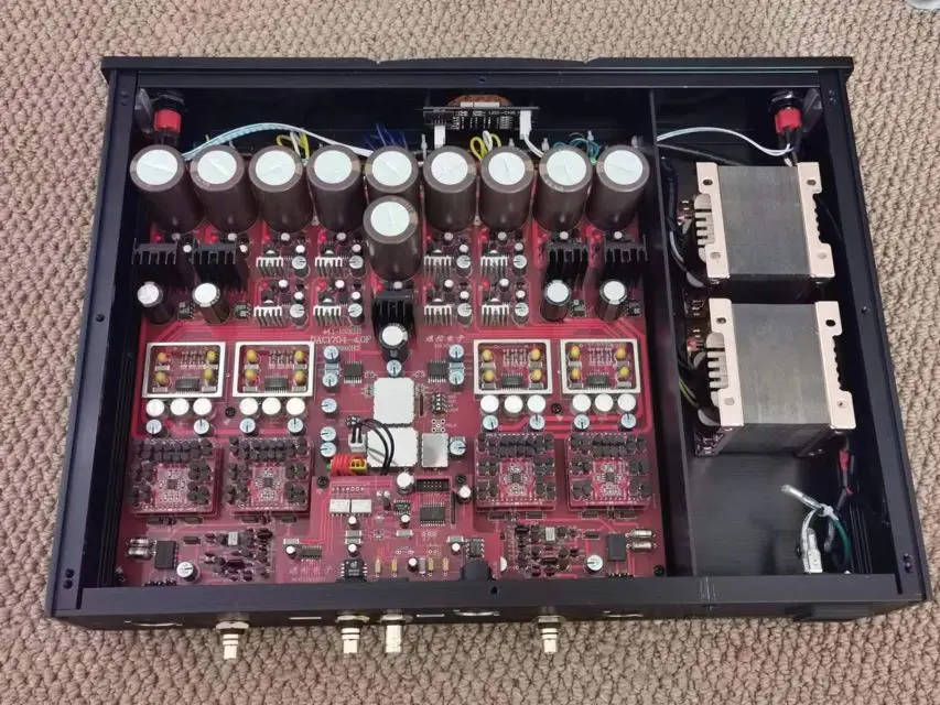
1) Adopting an integrated design, each power supply is strictly separated. The digital receiving and processing part has two sets of rectifier stabilized power supplies, and the decoding part has eight sets of stabilized power supplies for left and right independent power supply. The analog left and right independent power supply has a total of four sets of stabilized power supplies.
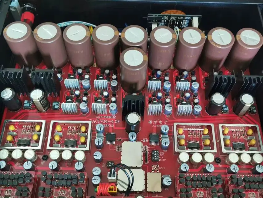
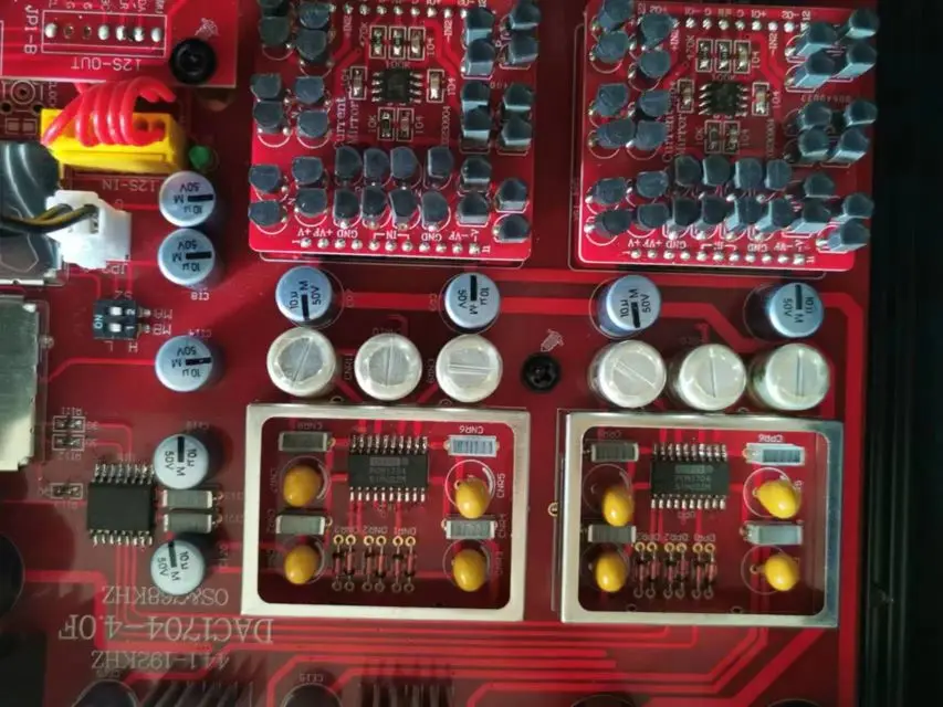
2) Circuit architecture: AK4118+digital signal processing+dual femtosecond CHD957 crystal oscillator+low jitter clock distribution circuit+DF 1706+digital isolation+PCM1704x4+four-way current mirror IV conversion circuit+four-way JFET transistor Class A output (balanced output)+two-way classic HDAM circuit (unbalanced output)
3) Signal input (44.1-192KHZ/24BIT):
1) AES
2) BNC
3) RCA
4) Fiber optic
5) 12S
The whole machine adopts software control, digital display, and single button selection of input channel.
5) Selection of components for motherboard:
A: The digital part uses high-precision wafer mounted audio resistors, and the capacitors use Philips water Blue shell electrolysis, Sibi electrolysis+Siemens layered cake.
B: The DA part adopts Sibi or UCC electrolysis+Siemens layered cake.
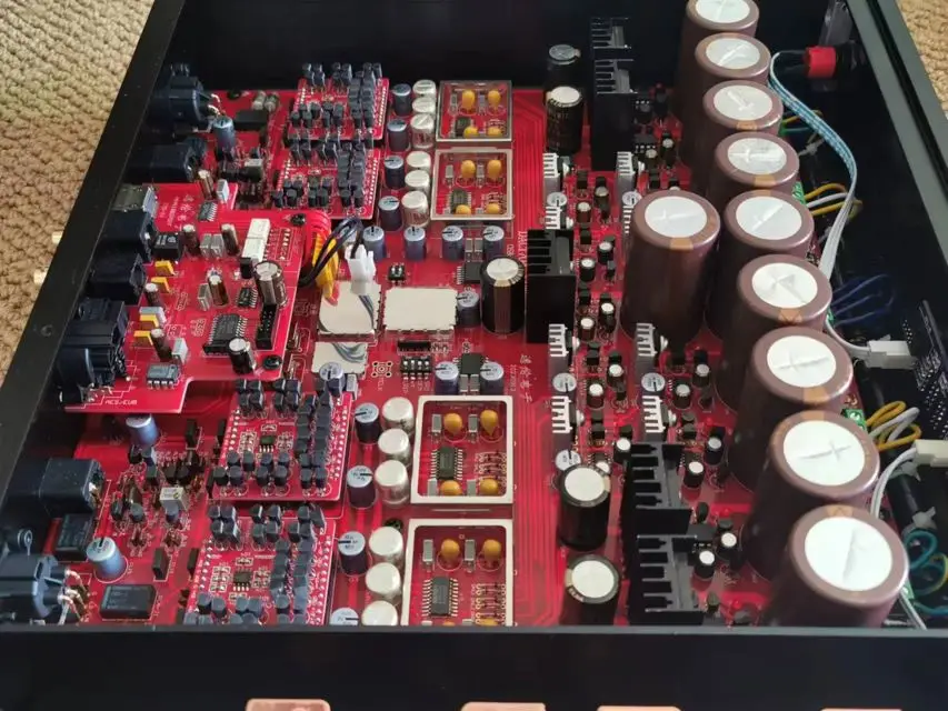
C: Ten ELNA Brown God II filters are selected for voltage stabilization circuit electrolysis. Nissan's ultra-low internal resistance rectifier tube uses wafer audio chip resistors as resistors, and a total of fourteen high-precision instrument grade precision reference sources are used. The whole machine uses fourteen sets of high-precision low ripple stabilized power supplies.
D: All resistors in the simulation section are Nissan photoacoustic insensitive sheet resistors. The transistors are made of Philips low-noise frequency transistors and Toshiba K170 and J74 field-effect transistors. All transistors are precisely paired using a graphical instrument, especially in the current mirror module, with the selection standard being the coincidence of four characteristic curves in a group.
6) Simulated voltage stabilization:
The analog amplification power supply adopts 2 sets of independent positive and negative 15V discrete voltage stabilizing boards (independent power supply for left and right channels), and the capacitors adopt Sibi or UCC+Siemens Qianceng Gao. The rectifier tube adopts ultra-low internal resistance Nissan D3S tube, and the transistor adopts American made low-noise frequency tube+Anson American audio power tube (the transistor selection for the digital voltage regulation part is the same as this)
Overall dimensions:
All aluminum chassis, width 430, height 78 (including legs), depth 320 (including input/output sockets), weight approximately 5 kilograms
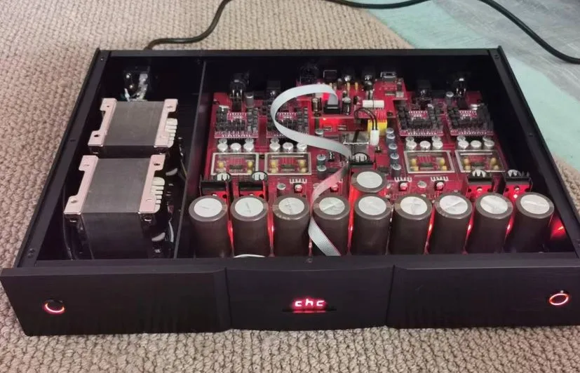
The whole machine adopts dual cow power supply, divided into two types: EI cow+Shimin oxygen free copper 0 cow.
The chassis is a small batch customized version, so there are no functional text annotations on the front and rear panels.
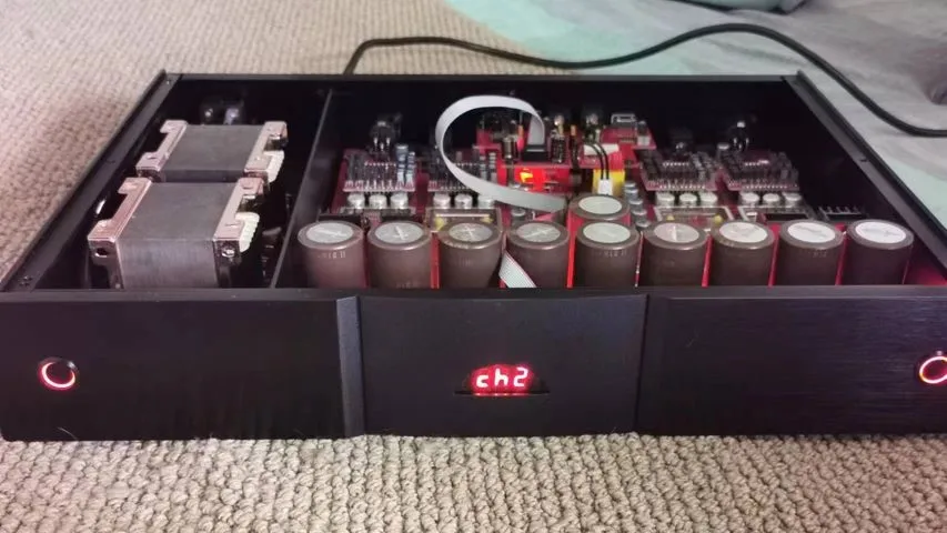
The left button is the power switch, and the right button is the input channel selection switch.
CH1 is AES, CH2 is BNC, CH3 is RCA, CH4 is optical fiber, and CH5 is I2S. CH1-CH4: If there is no signal, characters 1-4 will flash rapidly. If the signal is locked, it will stay on for a long time. If CH5 is selected, it will remain on for a long time.
Output: Two sets of balanced XLR, two sets of RCA output.
EI transformer
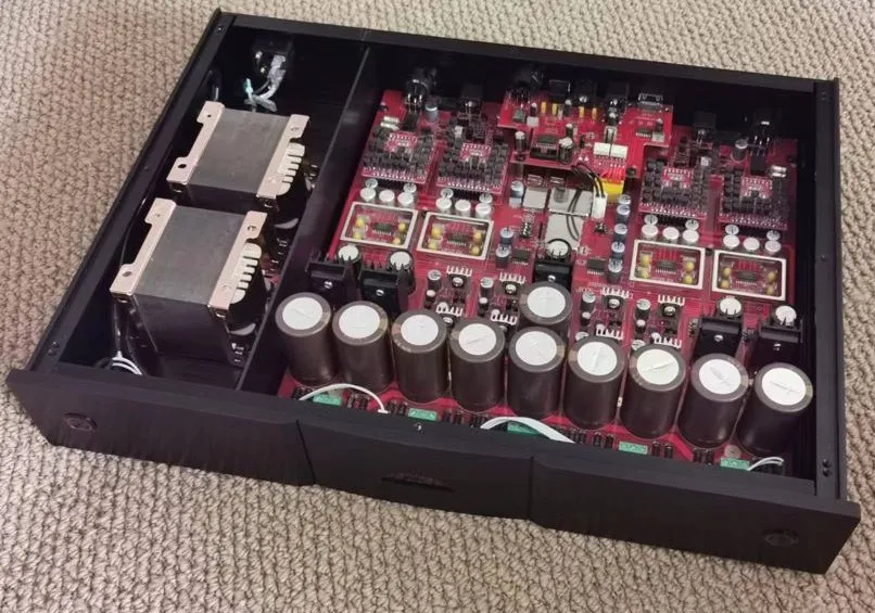
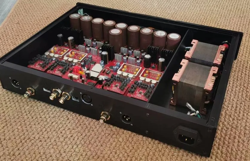
O-type transformer